Introducing the DÆ Output Board v1.0. Previous versions of my phono preamp used op-amps for the final output stage. This board is the first version of a dedicated output board that is all discrete and we know that all discrete sounds better -right? Well anyway, I always like designing new (at least to me) analog circuits so I went ahead with the design of an all discrete output board.
DÆ v1.0 Output Board
In building this board I wanted to try a few ideas. The board actually has two push-pull class-A output buffers; one for the non-inverting output of the XLR connector and the RCA connector and the second buffer is inverting for you guessed it, the inverting output of the XLR connector.
The buffer circuit design is very loosely based on the output stage of the Musical Fidelity A1. This amplifier from the 1980s was noted for two things; good sound and heat. It ran really hot. The circuit above does not run hot at all because it is the output stage of a pre-amp instead of a power amplifier. Actually the output transistors on the DÆ Output stage don’t even require a heat sink.
The circuit shows the output stage (click the word “circuit” to see the schematic with the output stages on pages two and three) with the collectors of the two output transistors connected to the output terminal which is different than a more common arrangement where the output transistor emitters are connected to the output terminal. I found the idea of connecting the collectors to the output terminal very interesting and wanted to try it out.
Emitter follower circuits (emitters connected to the output terminal) have a low output impedance which makes sense for an amplifier with a voltage output. You would expect the output impedance of a circuit with collectors connected to the output terminal to be high which is more typical of a current output. To my understanding the feedback loop makes the stage useful as a voltage amplifier. Yes, the circuit has global negative feedback - sorry about that for the passionate feedback deniers. But perhaps this arrangement had something to do with the legendary good sound of the Musical Fidelity A1 - but maybe not. Anyway I was interested to try this out and the measured performance of this simple topology is very good.
Left: Common-Collector also known as Emitter-Follower which is commonly seen in output stages. Right: Common-Emitter which is rare but out of interest used in DÆ Output stage.
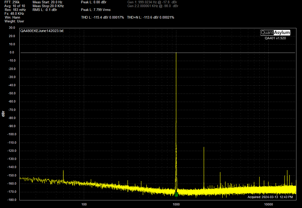
The figure below shows the measured response with a 1 kHz 1 volt RMS input. The output voltage between the non-inverting and inverting pins of the XLR output is 2 volts RMS. The distortion is -115 dB (0.00017%) which I think is quite good considering the simplicity of the circuit.
Measured response of the DÆ Output Board v1.0 at 1 kHz. This is for the XLR output with 1 volts RMS input and 2 volts RMS output between the XLR non-inverting and inverting terminals.
A couple notes about this measurement - it was taken with a QuantAsylum QA401 analyzer and QA480 1 kHz Oscillator + Notch filter. The QA480 Oscillator is a low distortion 1 kHz oscillator with distortion of -105 dB (0.006%). When the output of the Device Under Test (DUT) is passed through the QA480 Notch filter distortion measurements better than -140 dB (0.00001 %) are possible.
The Notch filter of the QA480 has a single-ended BNC input. To measure the performance of the differential XLR output I built a differential input instrument using an array of six LM4562 dual opamps making a total of twelve opamps. This differential input instrument has distortion and noise performance commensurate with the QA480 1 kHz Oscillator + Notch filter. The differential input instrument will be the subject of a future blog post. I plan to use this differential input design for the next version of my pre-amp which is the major project I have in mind for this year.
Specifications (actually measured) for the DÆ Output Board v1.0 are as follows:
The noise of the DÆ Output Board v1.0 is in the range 1 µV or one millionth of a volt. This is the total unweighted noise over the audio band. Measuring noise levels this low is a challenge because this is so close to the background noise of the test equipment. The measured noise of the QA401 Analyzer alone is 1.75 µV with it’s input shorted with a 50 Ω terminator.
Adding the LM4562 differential input instrument to the measurement chain increases the noise to 1.9 µV or just barely above the noise of the QA401 Analyzer alone. To estimate the noise contribution of the LM4562 differential input instrument alone requires an RMS subtraction of the two noise readings - which yields 0.74 µV. This type of subtraction is fraught with danger and can only be considered a very rough estimate. This is really a testimony to the tiny amount of noise introduced to the measurment by the LM4562 differential input instrument.
When the DÆ Output Board v1.0 (the Device Under Test) is added to the measurement chain the noise increases to 2.19 µV total from the RCA output with the input of the Device Under Test shorted. An RMS subtraction results in a noise estimate of 1.09 µV for the DÆ Output Board v1.0. I’m pretty happy with this again considering how simple the circuit is.


